Data centre backbone
High-fibre-count links between main, horizontal and zone distribution areas.

MTP/MPO TRUNK CABLE FOR HIGH-DENSITY DATA CENTRE BACKBONE AND PARALLEL-OPTICS CABLING.
Select the connector, fibre grade and cable construction for the intended link. The final order specification identifies the selected options and applicable limits.
| Fibre count | 8–144 fibres |
|---|---|
| Fibre modes | OS2 / OM3 / OM4 / OM5 |
| Connector options | MTP / MPO male or female |
| Polarity options | Type A / Type B / Type C |
| Cable jacket | OFNP / LSZH / PVC |
| Single-cable diameter | 3.0 mm |
| Connector options by brand | US Conec MTP / Senko MPO Plus |
| Cable jacket options | Plenum (OFNP) / LSZH / riser PVC |
| Elite low-loss connector option | 0.35 dB; specify the required connector grade |
|---|---|
| Termination | Factory terminated and tested |
| Minimum bend radius | Single-mode 10.0 mm; multimode 7.5 mm |
|---|---|
| Operating temperature | -10°C to +70°C |
| Storage temperature | -40°C to +85°C |
High-fibre-count links between main, horizontal and zone distribution areas.
MTP/MPO links selected for the transceiver, cassette or panel interface.
Structured cabling paths supporting staged 10G, 40G and 100G deployment.
Specify fibre count, MTP/MPO gender, polarity and overall length. The drawing shows the connector, boot, serial label and cable jacket.
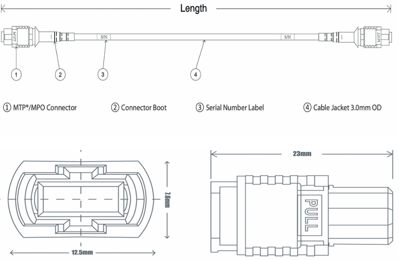
The single-cable construction is 3.0 mm. Larger bundled assemblies use the following trunk diameters; confirm the selected construction with the order.
| Bundles | MTP/MPO-12 fibre count | MTP/MPO-24 fibre count | Trunk diameter |
|---|---|---|---|
| 2 | 24 | 48 | 7.2 mm |
| 3 | 36 | 72 | 9.3 mm |
| 4 | 48 | 96 | 9.5 mm |
| 6 | 72 | 144 | 11.7 mm |
| 8 | 96 | — | 12.01 mm |
| 12 | 144 | — | 17.3 mm |
Match fibre grade, connector gender, alignment pins and Type A, B or C polarity across the full link. A trunk connects multi-fibre interfaces; a breakout distributes fibres to individual connector legs.
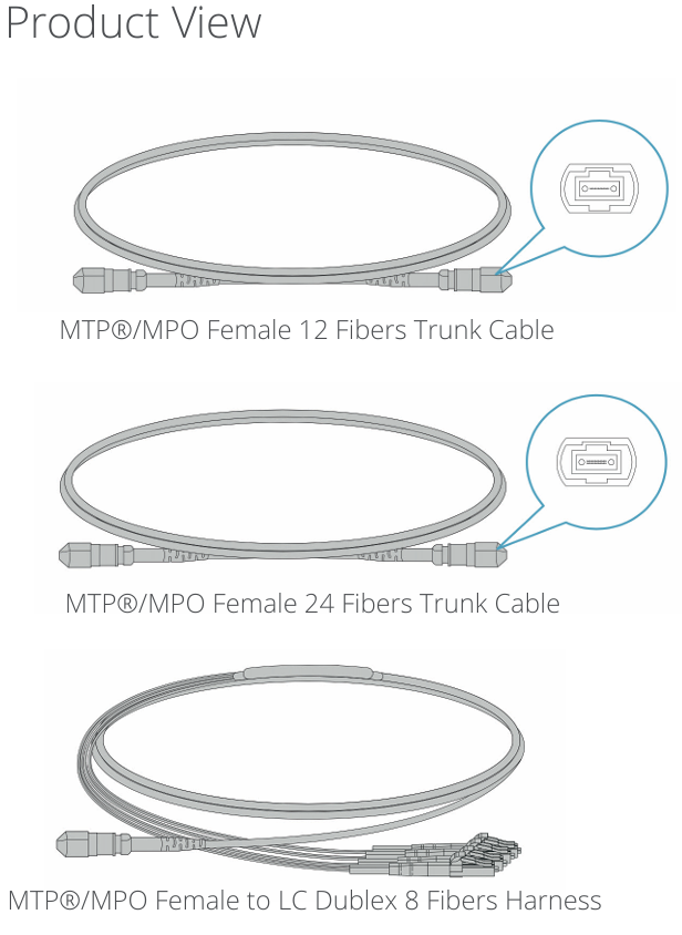
Inspect the full multi-fibre end face, clean with an appropriate MTP/MPO cleaner and verify the pin arrangement before insertion. Keep the connector key aligned with the receiving port.
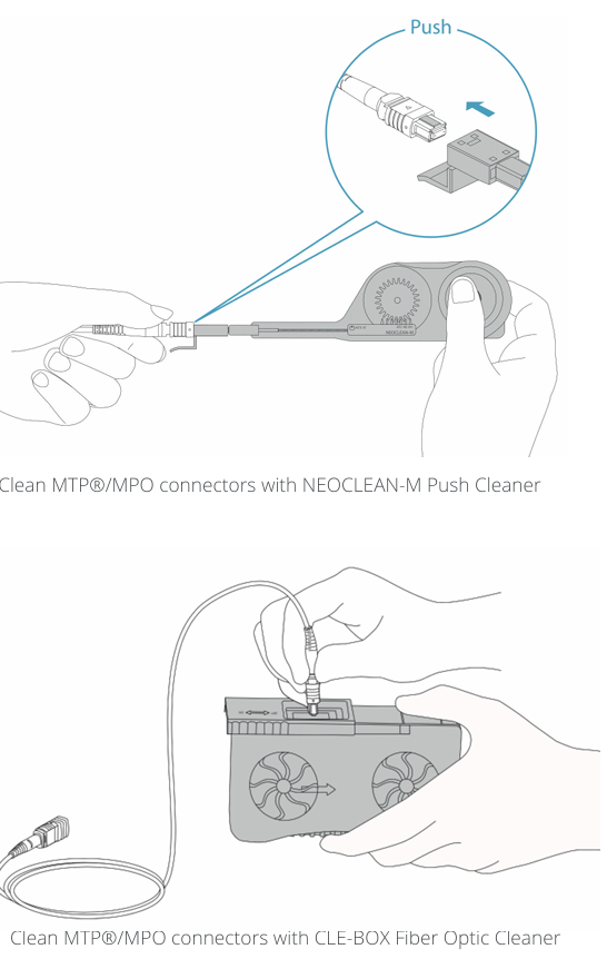
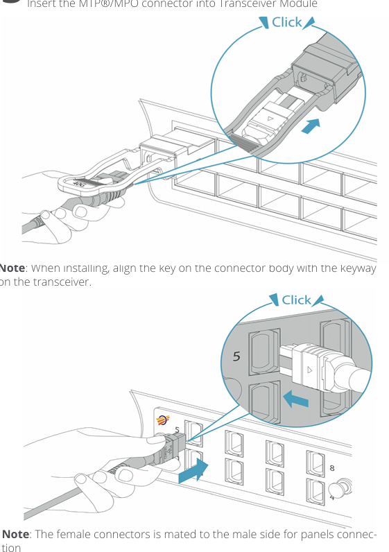
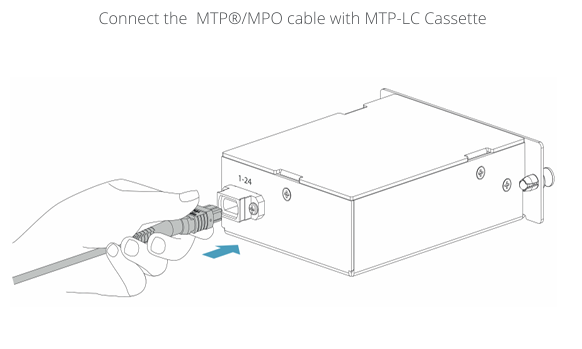
Confirm the cassette polarity and the matching connector gender before connecting the trunk.
Compare fibre grades and optical interfaces from 1G to 100G. These are link-planning references; cable length alone does not determine supported reach.
| Data rate | Interface | Fibre mode | Wavelength | Reference distance |
|---|---|---|---|---|
| 1G | 1000BASE-SX | OM1 / OM2 / OM3 / OM4 | 850 nm | OM1: up to 275 m; OM2/OM3/OM4: up to 550 m |
| 1G | 1000BASE-LX/LH | MMF / OS2 | 1310 nm | MMF: up to 550 m with the required launch conditions; 10 km-rated LX/LH module: 10 km on OS2 |
| 10G | 10GBASE-SR | OM1 / OM2 / OM3 / OM4 | 850 nm | OM1: 33 m; OM2: 82 m; OM3: 300 m; OM4: 400 m |
| 10G | 10GBASE-LRM | OM1 / OM2 / OM3 | 1310 nm | Up to 220 m; fibre bandwidth and mode-conditioning requirements apply |
| 10G | 10GBASE-LR | OS2 | 1310 nm | 10 km |
| 10G | 10GBASE-ER | OS2 | 1550 nm | Up to 40 km; verify the optical power budget |
| 10G | ZR long-reach optics | OS2 | 1550 nm | 80–100 km, depending on the selected module and link budget |
| 40G | BiDi | OM3 / OM4 / OM5 | Module-specific paired wavelengths | OM3: 100 m; OM4: 150 m; OM5: up to 200 m with a compatible module |
| 40G | 40GBASE-SR4 | OM3 / OM4 / OM5 | 850 nm | OM3: 100 m; OM4/OM5: 150 m |
| 40G | SWDM4 | OM3 / OM4 / OM5 | 850–940 nm | OM3: 240 m; OM4: 350 m; OM5: 440 m for the specified SWDM4 module |
| 40G | 40GBASE-LR4 | OS2 | 1310 nm band | 10 km |
| 100G | 100GBASE-SR4 | OM3 / OM4 / OM5 | 850 nm | OM3: 70 m; OM4/OM5: 100 m |
| 100G | SWDM4 | OM3 / OM4 / OM5 | 850–940 nm | OM3: 75 m; OM4: 100 m; OM5: 150 m for the specified SWDM4 module |
| 100G | 100GBASE-SR10 | OM3 / OM4 | 850 nm | OM3: 100 m; OM4: 150 m |
| 100G | 100GBASE-LR4 | OS2 | 1310 nm band | 10 km |
| 100G | 100GBASE-ER4 | OS2 | 1310 nm band | 40 km |
Use the exact transceiver specification, fibre bandwidth, connector loss and installation conditions to confirm the link. BiDi, SWDM4 and extended-reach results depend on the selected module. Parallel optics also require the correct fibre count and polarity.
Specify fibre grade and count, MTP/MPO gender, polarity, connector ends, jacket, overall length, any fan-out length and quantity.
Supported reach depends on the transceiver interface, fibre bandwidth, installed-link loss and application. Use the comparison table for initial selection, then check the exact transceiver specification.
Match Type A, B or C polarity, connector gender and key orientation to the transceiver, cassette and patching design. Verify the whole link before ordering.
Include the selected configuration and required inspection records in your enquiry. The applicable test scope and document format are confirmed for that assembly.
Send the connector ends, fibre grade, length, jacket, quantity and any polarity, labelling or inspection requirements.
Move from model selection to internal approval with the documents, compatibility checks and verification paths buyers use most.
 01Technical files
Find model-level specifications, drawings and selection documents before internal review.
Find datasheets 02Device fit
Review device, firmware and coding fit before specifying a module for your network.
Check compatibility 03Verification
See optical, functional and pre-shipment checks used to verify product performance.
Review testing 04Project approval
Review certification routes and request supporting documents for project approval.
View documents