100G QSFP28 BREAKOUT DAC

100G QSFP28 TO 4X25G SFP28 1m

Rate100G ~25GReach1mWavelength-Interface-
Fiberland part number
FLD-Q28-DAC-BO1M
Unit priceAsk Our Manager

Key Specifications

Select a specification to see how it affects model selection.

View complete table
Form TypeQSFP28 - SFP28

Check this recorded value against the target device and project requirements before quotation approval.

Technical Specifications

Filter the product record by the information needed for engineering or purchasing review.

14 specifications shown
Fiberland Part NumberFLD-Q28-DAC-BO1MVendor NameFIBERLAND
Data Rate100G ~25GWavelength-
Reach1mForm TypeQSFP28 - SFP28
Optical Interface-DDM Support-
Commercial Temp.0~70℃Industrial Temp.-
Compatible BrandsCisco,Huawei,Nvidia...200+ brandsComplianceCE,FCC,ROHS,REACH
Warranty3 YearsMode-

Product Compatibility Mapping

Cross-reference the original manufacturer part number with the corresponding Fiberland part number before confirming the target device and firmware.

Search Full Compatibility Database
Verified cross-references12 manufacturer part numbersAcross 7 brands
Showing 8 of 12 verified matches

Swipe horizontally to view every field.

Original part numberBrandFiberland part numberProduct description
QSFP-4SFP25G-CU1MCISCOFLD-Q28-DAC-BO1M100G QSFP28 to 4 x 25G SFP28 passive direct-attach copper breakout cable, 1 m.
CAB-Q-4S-100G-1MARISTAFLD-Q28-DAC-BO1M100G QSFP28 to 4 x 25G SFP28 passive direct-attach copper breakout cable, 1 m.
JNP-100G-4X25G-1MJUNIPERFLD-Q28-DAC-BO1M100G QSFP28 to 4 x 25G SFP28 passive direct-attach copper breakout cable, 1 m.
720-068901JUNIPERFLD-Q28-DAC-BO1M100G QSFP28 to 4 x 25G SFP28 passive direct-attach copper breakout cable, 1 m.
MCP7F00-A001RNVIDIAFLD-Q28-DAC-BO1M100G QSFP28 to 4 x 25G SFP28 passive direct-attach copper breakout cable, 1 m.
MCP7F00-A001R30NNVIDIAFLD-Q28-DAC-BO1M100G QSFP28 to 4 x 25G SFP28 passive direct-attach copper breakout cable, 1 m.
02311MNXHUAWEIFLD-Q28-DAC-BO1M100G QSFP28 to 4 x 25G SFP28 passive direct-attach copper breakout cable, 1 m.
QSFP-100G-4SFP-25G-CAB-1MH3CFLD-Q28-DAC-BO1M100G QSFP28 to 4 x 25G SFP28 passive direct-attach copper breakout cable, 1 m.

A part-number cross-reference is a model-selection starting point, not a blanket device guarantee. Final fit depends on the exact device, firmware or OS, target port and requested coding profile.
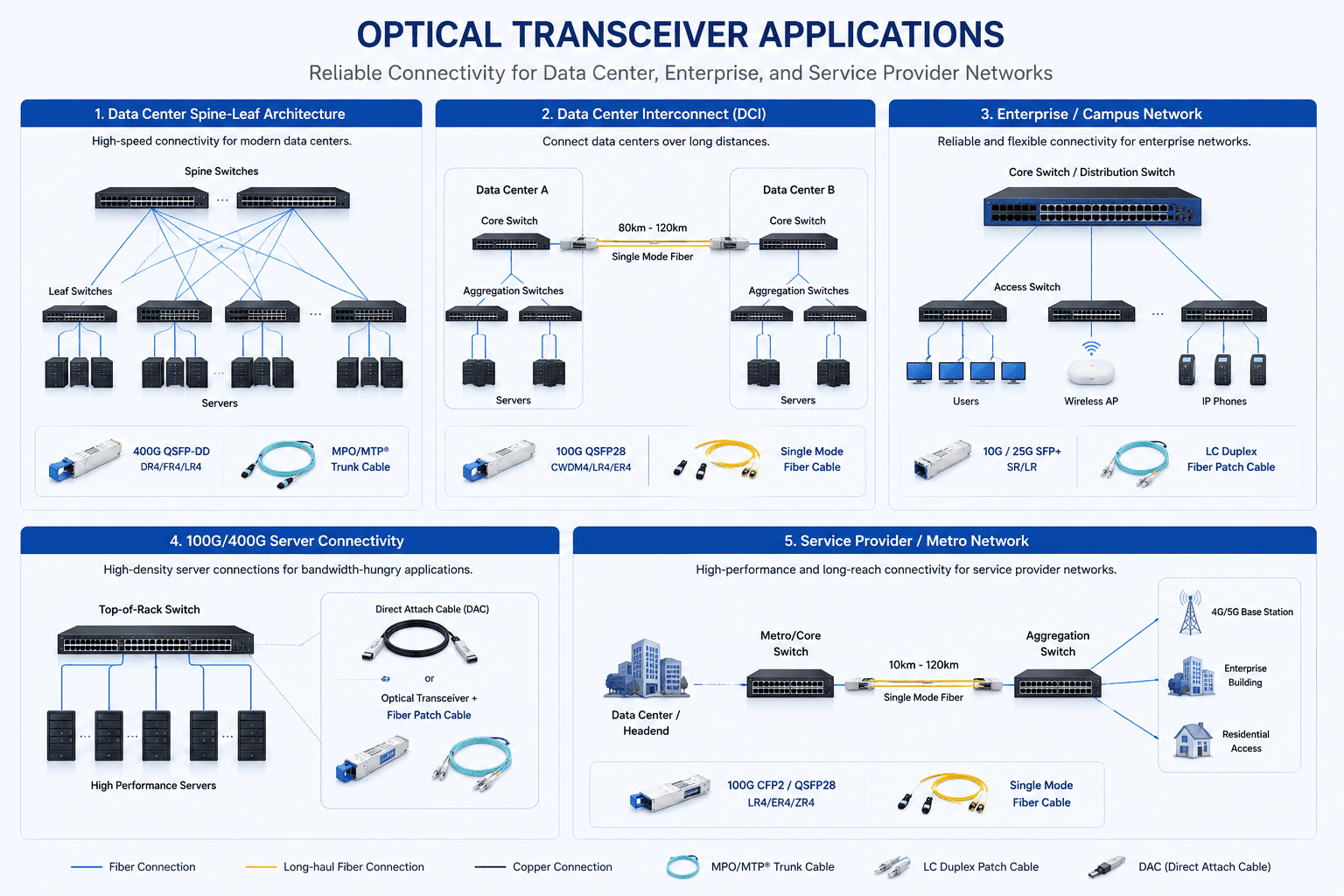
See Where This Product Fits in the Network

Review common data-center, DCI, campus, server and metro-network connections before confirming speed, reach, fiber type and connector.

Application planning

Optical Transceiver Application and Link Map

Compare representative network topologies and link paths to identify the appropriate product family for the intended deployment.

View full application diagram
Optical transceiver application diagram covering data center, DCI, campus, server and metro networks

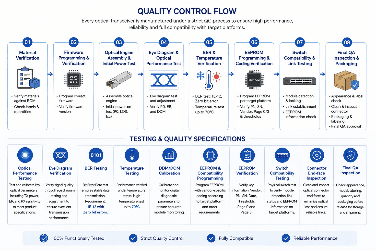
Review the Quality-Control and Test Flow

Follow the checkpoints used to verify materials, firmware, optical performance, temperature stability, compatibility and final inspection.

Testing and quality

Quality Control and Test Flow

Review the sequence from material verification and firmware programming through optical, temperature, compatibility and final QA inspection.

View full testing diagram
Quality control flow covering material, firmware, optical, temperature, compatibility and final QA checks

Frequently Asked Questions

Answers to common compatibility, installation and troubleshooting questions.

Does the OEM part number need to match exactly?

The exact OEM reference is useful for identifying compatibility, but the optical specifications and host-platform requirements must also match the intended application.

Do both ends of an optical link need the same OEM compatibility?

No. Each transceiver generally needs to be compatible with the equipment in which it is installed. For example, one end may be coded for one switch brand and the other end for another.

What is the difference between equipment compatibility and optical compatibility?

Equipment compatibility determines whether the host device recognizes and operates with the module. Optical compatibility determines whether the two ends of the fiber link can communicate correctly. A successful deployment requires both.

Why is there no TX optical power from the compatible transceiver?

Check whether the port is administratively enabled and whether the host has disabled the transmitter because of an unsupported-module condition or configuration issue. If the module is correctly recognized and enabled, further hardware testing may be required.

Why is EEPROM programming important for compatibility?

Network equipment may inspect the module's EEPROM information before allowing normal operation. Correct programming helps the host identify and manage the transceiver properly.

Tell Us What Your Project Needs

Engineering resources

Technical proof for faster project review

Move from model selection to internal approval with the documents, compatibility checks and verification paths buyers use most.