Transceiver Adapters

CVR-X2-SFP10G,Cisco X2 to SFP+ Converter Module

Fiberland is a leading manufacturer of Cisco compatible X2 to SFP+ CONVERTER ,CVR-X2-SFP10G transceiver. Based on the full stock of CVR-X2-SFP10G,we are able to arrange your shipping within 2 business days for quantity under 300 pcs. We 100% guarantee that the CVR-X2-SFP10G transceiver which we produced is compatible with original Cisco X2 to SFP+ CONVERTER module.The CVR-X2-SFP10G transceiver comes with a 3 years warranty and lifetime maintenance. The Fiberland CVR-X2-SFP10G is a level first and Class 1 laser product.It's fully comply with the multi sourcing agreement.All the CVR-X2-SFP10G will be fully tested with original brand switch with standard 8 hours before shipping. The CVR-X2-SFP10G is with CE,FCC,ROHS verified.

Rate10GReachN/AWavelengthN/AInterfaceN/A
Fiberland part number
FLD-CVR-X2-SFP10G-C

Key Specifications

Select a specification to see how it affects model selection.

View complete table
Form TypeX2 TO SFP+ CONVERTER

Check this recorded value against the target device and project requirements before quotation approval.

Technical Specifications

Filter the product record by the information needed for engineering or purchasing review.

14 specifications shown
Vendor NameFiberlandForm TypeX2 TO SFP+ CONVERTER
Data Rate10GWavelengthN/A
ReachN/AOptical InterfaceN/A
Media TypeN/ADDM SupportN/A
Commercial Temp.0~70℃Industrial Temp.N/A
Compatible BrandsCiscoCertificatesCE,FCC,ROHS,REACHFLD
HS Code8517706000Warranty3 Years

Product Compatibility Mapping

Cross-reference the original manufacturer part number with the corresponding Fiberland part number before confirming the target device and firmware.

Search Full Compatibility Database

No verified part-number mapping is linked to this product yet.

Send the target device brand, model, firmware or OS and port details for an exact compatibility review.

A part-number cross-reference is a model-selection starting point, not a blanket device guarantee. Final fit depends on the exact device, firmware or OS, target port and requested coding profile.

See Where This Product Fits in the Network

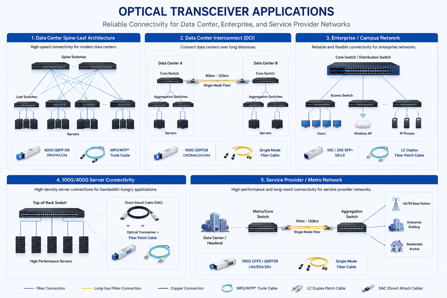
Review common data-center, DCI, campus, server and metro-network connections before confirming speed, reach, fiber type and connector.

Application planning

Optical Transceiver Application and Link Map

Compare representative network topologies and link paths to identify the appropriate product family for the intended deployment.

View full application diagram
Optical transceiver application diagram covering data center, DCI, campus, server and metro networks

Review the Quality-Control and Test Flow

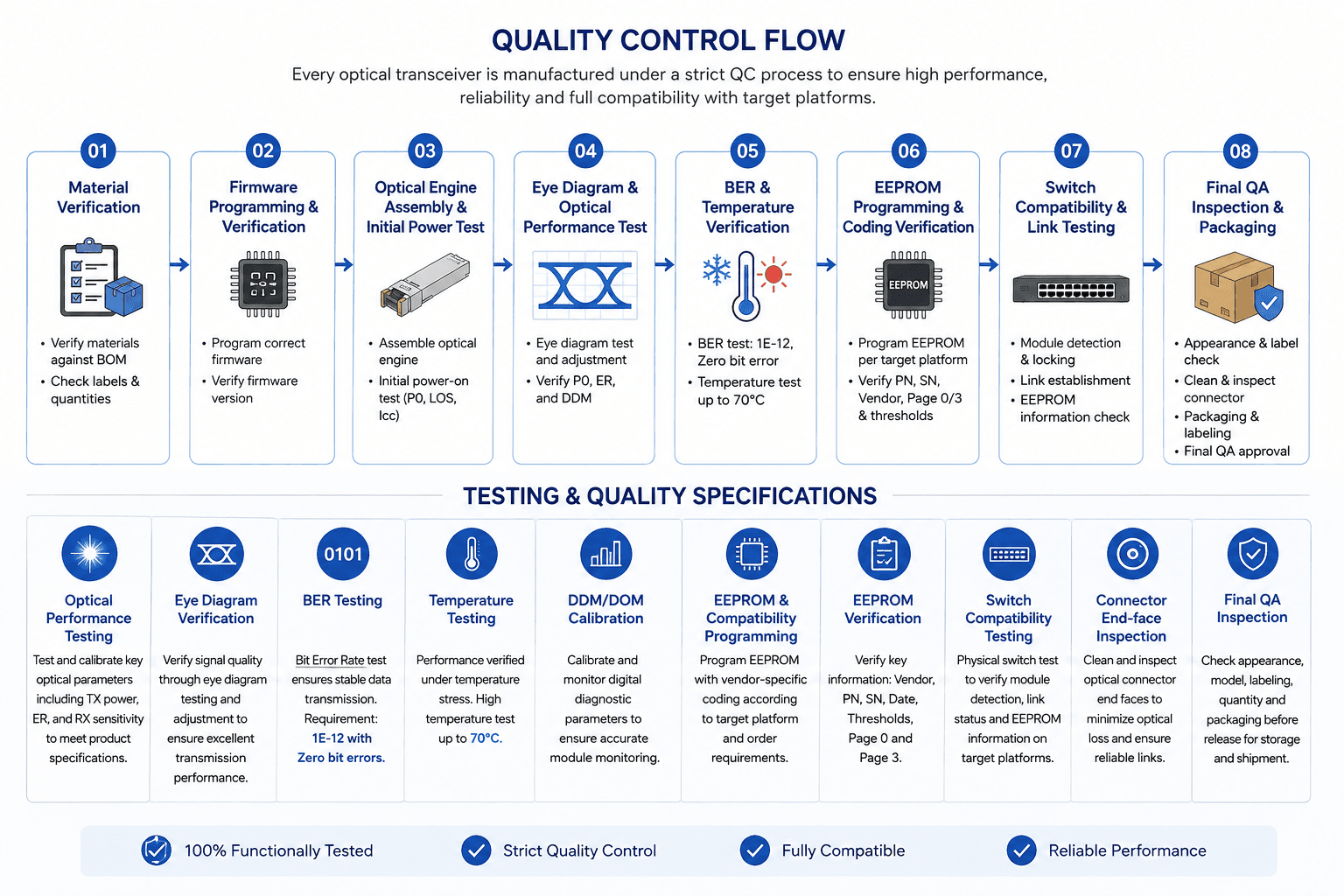
Follow the checkpoints used to verify materials, firmware, optical performance, temperature stability, compatibility and final inspection.

Testing and quality

Quality Control and Test Flow

Review the sequence from material verification and firmware programming through optical, temperature, compatibility and final QA inspection.

View full testing diagram
Quality control flow covering material, firmware, optical, temperature, compatibility and final QA checks

Frequently Asked Questions

Answers to common compatibility, installation and troubleshooting questions.

Can compatible transceivers be used for 100G, 400G, and 800G networks?

Yes. Compatible modules are available across many high-speed interfaces, although compatibility requirements become increasingly platform-specific at higher data rates.

Will DOM values appear correctly on third-party transceivers?

With a properly compatible module and supported host platform, DOM/DDM values should normally be accessible through the network equipment's management interface.

Can one optical transceiver be compatible with multiple brands?

Yes. The same optical hardware may support multiple equipment brands when it is programmed with the appropriate compatibility profile. Multi-vendor coding options may also be available for certain applications.

Why does my compatible transceiver show low RX optical power?

Low receive power can result from excessive fiber loss, dirty connectors, damaged fiber, excessive link distance, incorrect wavelength pairing, or insufficient transmit power from the remote transceiver. Compare the measured RX power with the module's specified receiver range.

Why are the DDM/DOM readings incorrect or abnormal?

Abnormal temperature, voltage, TX power, RX power, or bias-current readings may indicate an optical or hardware issue, but they can also result from incorrect calibration or communication between the compatible module and host device.

Tell Us What Your Project Needs

Engineering resources

Technical proof for faster project review

Move from model selection to internal approval with the documents, compatibility checks and verification paths buyers use most.