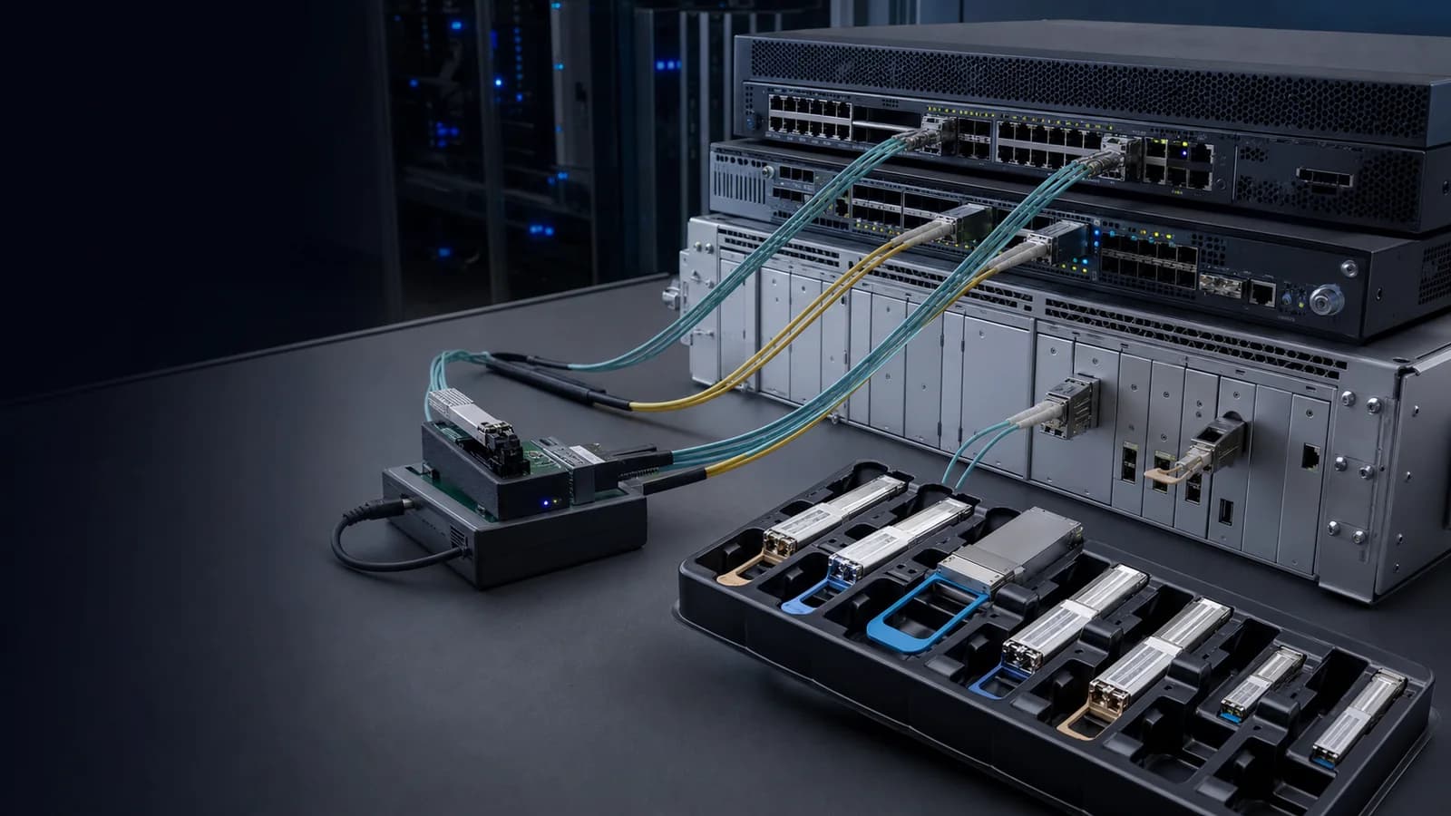
1G SFP Transceivers

2.5G,3G,4.25G Dual Fiber SFP

Rate2.5G,3G,4.25GAvailable reaches500m / 5km / 10km / 20km / 40km / 60km / 80km / 120kmWavelength850/1310/1550nmInterfaceDuplex LC
Fiberland part number
FLD-S2.5G-MMD-1

Key Specifications

Select a specification to see how it affects model selection.

View complete table
Form TypeSFP

Check this recorded value against the target device and project requirements before quotation approval.

Technical Specifications

Filter the product record by the information needed for engineering or purchasing review.

14 specifications shown
Vendor NameFiberlandForm TypeSFP
Data Rate2.5G,3G,4.25GWavelength850/1310/1550nm
Available reaches500m / 5km / 10km / 20km / 40km / 60km / 80km / 120kmOptical InterfaceDuplex LC
Media TypeMM/SMDDM SupportOptional
Commercial Temp0~70℃Industrial Temp.-40~85℃
Compatible BrandsCisco,HP,Huawei,etc...CertificatesCE,FCC,ROHS,REACH
HS Code8517706000Warranty3 Years

Select an Exact Length or Reach

Choose one listed value to view only the part numbers recorded for that distance.

Fiberland part numberRateMediaWavelengthExact reachConnector
FLD-S2.5G-MMD-12.5GbpsMM850NM500MLC
FLD-S2.5G-SMD-202.5GbpsSM1310NM20KMLC
FLD-S2.5G-SMD-402.5GbpsSM1550NM40KMLC
FLD-S2.5G-SMD-802.5GbpsSM1550NM80KMLC
FLD-S2.5G-SMD-1202.5GbpsSM1550NM120KMLC
FLD-S3G-SMD-203GbpsSM1310NM20KMLC
FLD-S3G-SMD-403GbpsSM1550NM40KMLC
FLD-S3G-SMD-603GbpsSM1550NM60KMLC
FLD-S3G-SMD-803GbpsSM1550NM80KMLC
FLD-S3G-SMD-1203GbpsSM1550NM120KMLC
FLD-4G-MMD-500M4.25GMM850NM500MLC
FLD-4G-SMD-54.25GSM1310NM5KMLC
FLD-4G-SMD-104.25GSM1310NM10KMLC
FLD-4G-SMD-204.25GSM1310NM20KMLC
FLD-4G-SMD-404.25GSM1550NM40KMLC

15 model options shown.

Product Compatibility Mapping

Cross-reference the original manufacturer part number with the corresponding Fiberland part number before confirming the target device and firmware.

Search Full Compatibility Database

No verified part-number mapping is linked to this product yet.

Send the target device brand, model, firmware or OS and port details for an exact compatibility review.

A part-number cross-reference is a model-selection starting point, not a blanket device guarantee. Final fit depends on the exact device, firmware or OS, target port and requested coding profile.
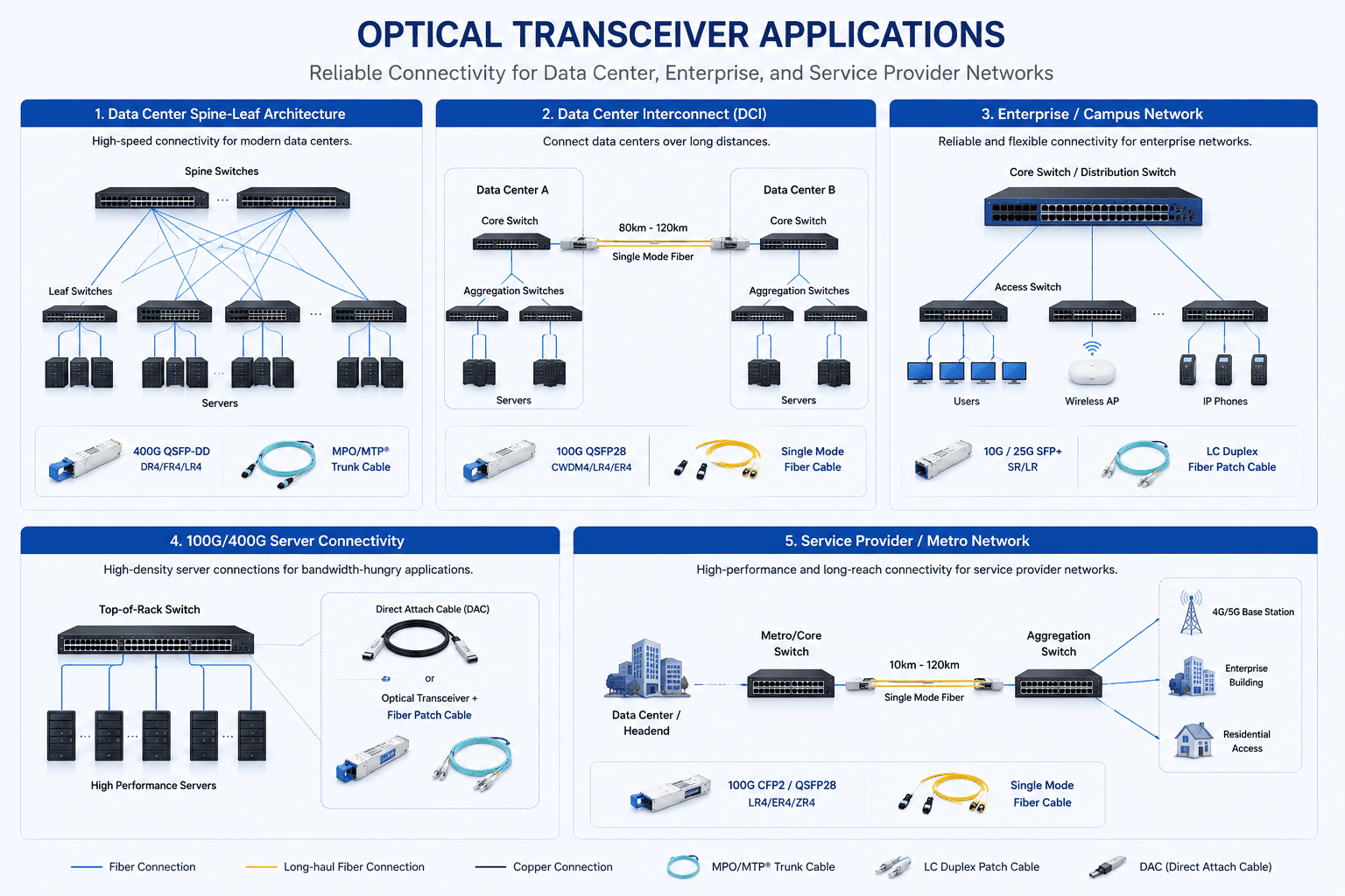
See Where This Product Fits in the Network

Review common data-center, DCI, campus, server and metro-network connections before confirming speed, reach, fiber type and connector.

Application planning

Optical Transceiver Application and Link Map

Compare representative network topologies and link paths to identify the appropriate product family for the intended deployment.

View full application diagram
Optical transceiver application diagram covering data center, DCI, campus, server and metro networks

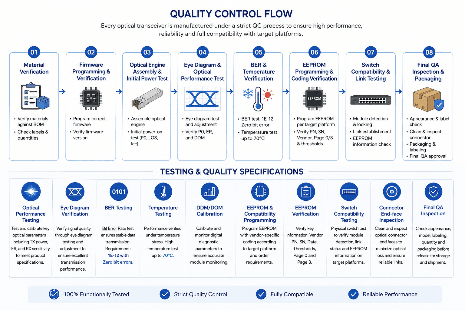
Review the Quality-Control and Test Flow

Follow the checkpoints used to verify materials, firmware, optical performance, temperature stability, compatibility and final inspection.

Testing and quality

Quality Control and Test Flow

Review the sequence from material verification and firmware programming through optical, temperature, compatibility and final QA inspection.

View full testing diagram
Quality control flow covering material, firmware, optical, temperature, compatibility and final QA checks

Frequently Asked Questions

Answers to common compatibility, installation and troubleshooting questions.

How do I find a compatible transceiver for an OEM part number?

Search using the OEM part number and verify the form factor, data rate, wavelength, transmission distance, connector, fiber type, and host-platform compatibility.

Will DOM values appear correctly on third-party transceivers?

With a properly compatible module and supported host platform, DOM/DDM values should normally be accessible through the network equipment's management interface.

Can a transceiver be compatible with the switch but still fail to link?

Yes. Host compatibility and optical-link compatibility are separate issues. A module may be correctly recognized while the link fails because of fiber, wavelength, FEC, polarity, configuration, or link-budget problems.

Why does my switch show an “unsupported transceiver” warning?

Some network devices validate vendor information stored in the transceiver EEPROM. If the module's coding is not recognized by the host platform, the switch may display an unsupported or non-certified transceiver warning.

Why does a high-speed compatible transceiver show FEC errors?

FEC errors may result from incompatible FEC settings, excessive optical loss, signal-quality problems, incorrect fiber infrastructure, or incompatible link parameters. Verify that both ends use the required FEC mode for the interface.

Tell Us What Your Project Needs

Engineering resources

Technical proof for faster project review

Move from model selection to internal approval with the documents, compatibility checks and verification paths buyers use most.