Application planning

Choose the optical path for every network link.

Compare rack, campus, data-center interconnect and access-network scenarios before selecting a transceiver, DAC, AOC or fiber assembly.

Data centerDCI & metroEnterpriseServer & storageAccess networks
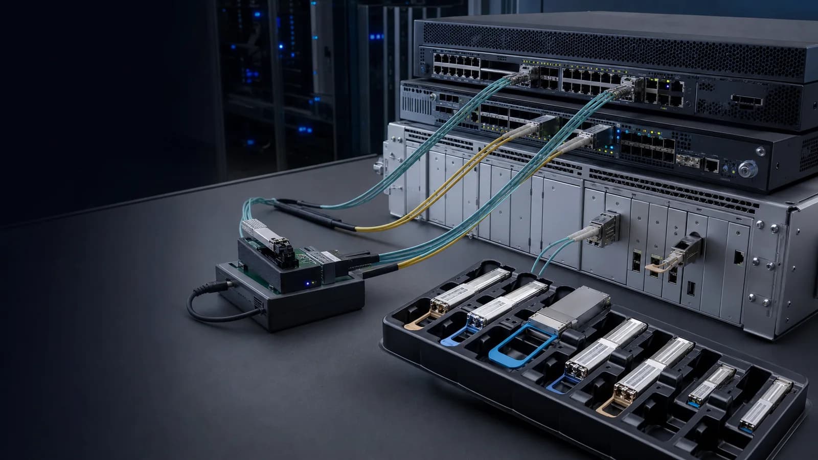
Optical links between network equipment for data center, campus and inter-site applications
Define the equipment, route and reach before matching the product family.

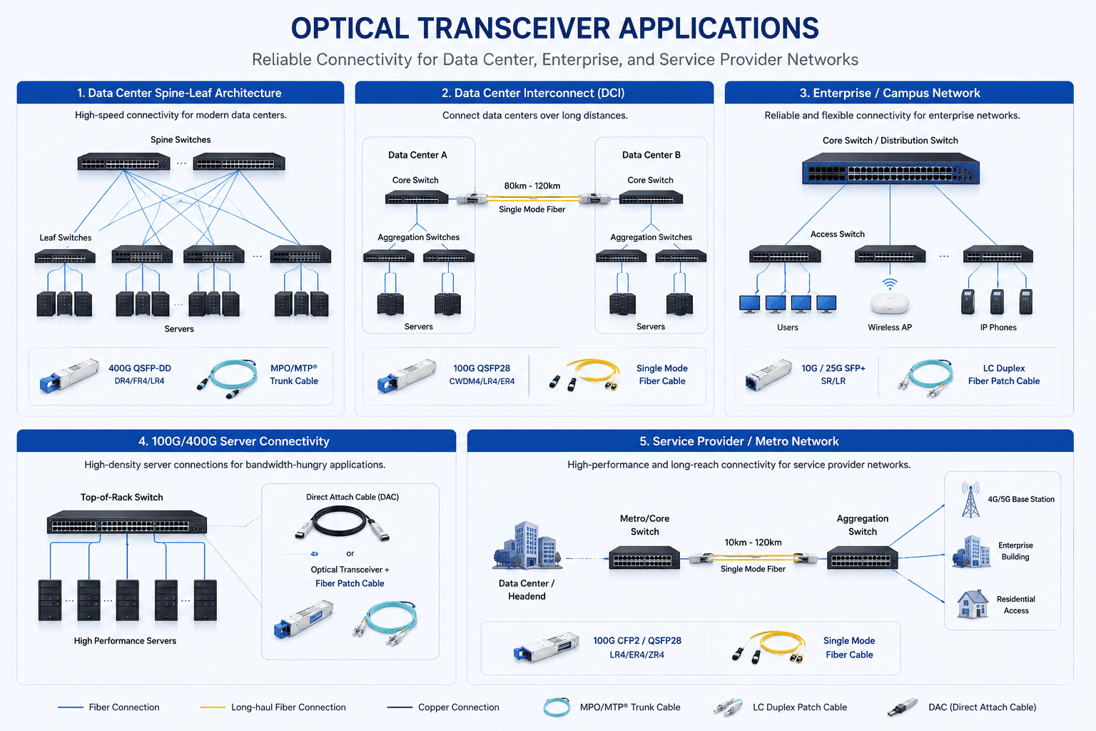
Optical Connectivity Across Five Network Scenarios

One project can contain short copper links, multimode server links, single-mode building links and long-reach transport paths. Review each link independently before choosing a model.

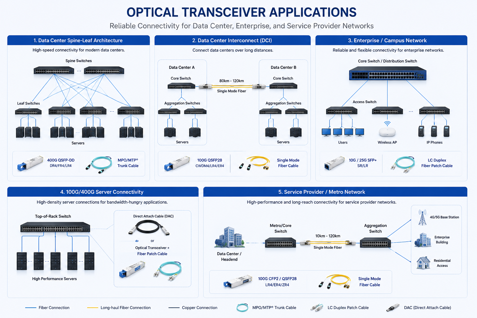
Optical transceiver application map for data center, DCI, campus, server and metro networks
Application diagram covering spine-leaf, data-center interconnect, enterprise campus, server connectivity and service-provider networks.View full diagram

Choose the Scenario Closest to Your Project

Use the cards as a starting point. Final product selection still depends on the exact device, port, fiber plant, environment and link budget.

01
Data center fabrics

Leaf-Spine and AI Cluster Links

Plan high-density switch-to-switch and switch-to-server links across leaf-spine fabrics, GPU clusters and storage networks.

High-speed opticsDAC / AOCMPO / MTP
Check before selectionPort speed, FEC and breakout modeRack, row and room link distances
Browse the product path

02
DCI and metro

Inter-Site Optical Links

Connect buildings, campuses or data-center sites over single-mode fiber with the reach and wavelength plan matched to the route.

Single-mode opticsCWDM / DWDMDuplex LC
Check before selectionEnd-to-end loss and distanceWavelength plan and fiber availability
Browse the product path
03
Enterprise and campus

Campus and Building Networks

Support access, distribution and core layers while reusing installed fiber where the link budget and interface allow it.

SFP / SFP+ / QSFPBiDi optionsPatch cords
Check before selectionInstalled fiber and connector typeSwitch model, software and target port
Browse the product path
04
Server and storage

High-Density Equipment Connections

Match top-of-rack, server and storage connections to the required lane count, density, latency and serviceability.

DACAOCBreakout assemblies
Check before selectionLane count and cable architectureServer NIC, HBA or switch requirements
Browse the product path
05
Access and transport

Service Provider and Edge Links

Plan aggregation, access and transport links for service-provider, wireless and edge networks with the required reach and environment.

Long-reach opticsCWDM / DWDMIndustrial options
Check before selectionOutdoor or industrial temperatureCoding, monitoring and compliance needs
Browse the product path

Link Inputs That Drive Model Selection

Use the same five inputs for every connection so the product family, compatibility check and document package stay tied to the actual network requirement.

Check Compatibility
  1. 01
    Platform

    Device and Port

    Record the equipment brand, exact model, software version, target port and supported data rate.

  2. 02
    Link

    Speed and Reach

    List each connection separately, including speed, distance, link direction and any breakout requirement.

  3. 03
    Fiber plant

    Fiber and Connector

    Confirm single-mode or multimode fiber, strand count, connector, polarity and available loss budget.

  4. 04
    Validation

    Compatibility

    Check vendor coding, DDM/DOM, FEC, wavelength pairing and interoperability at both ends.

  5. 05
    Project

    Environment and Supply

    Add operating temperature, compliance documents, quantity, destination and required delivery timing.

Review Your Network Requirement

Send the information already available. Fiberland can help narrow the product family, check the target platform and prepare the quotation and supporting documents.