
General Failure Mode Classification and Analysis of Optical Transceiver
2017-09-28
As a core device of optical communication, the performance and reliability of optical transceivers are always the two most concerned issues for suppliers and users. Some optical transceivers will fail due to problems in design, process fabrication, and engineering use. This article introduces the general failure mode classification and common failure modes of optoelectronic devices and optical transceivers.
Introduction
Optical communication technology to high-speed, high-capacity, small size, the high-density direction of development, new products continue to appear. In Gigabit optical access network, the High-speed optical transceiver module is the key component, and its performance and reliability are the two most concerned problems for the supplier and the user. The performance and reliability of optoelectronic devices and optical transceiver modules are not only related to product design, materials used, manufacturing conditions, process levels, working conditions and time, but also to the production environment and the fine spirit of the operators. In the industry competition, product reliability becomes more and more important.
For optoelectronic devices and optical transceivers, due to the structural tolerance has entered into the sub-millimeter (for PCB design), submicron (for optoelectronic chips) level, requiring the workpiece to be non-polluting, structurally complex processes long, and some products are defective or insufficient. These defects or deficiencies, in the harsh external conditions (such as temperature, humidity, stress, electromagnetic interference) will continue to expand, resulting in product features and photoelectric performance changes do not meet the requirements of the product requirements, resulting in product failure. The failure mode is the form of product failure, including in the force (mechanical), electricity, light, heat, magnetic, and the performance of the form. Through the detection, field use and reliability test, you can find a variety of product failure mode. The relevant international and domestic standards specify the reliability test and requirements for optoelectronic devices. Through the reliability test and failure analysis, the improvement measures and verification, product reliability is expected to continue to improve.
However, the reliability of some products has been solved and the reliability of new products has arisen. In this paper, we first introduce the General failure mode classification and common failure modes of optical communication optoelectronic devices/Optical transceiver modules and report and analyze two new failure modes in order to help to analyze the failure mechanism and propose improvement measures.
General failure mode classification and common failure modes of optical devices and transceiver
Many failure modes exist in optical communication in optical devices and optical transceiver modules. According to the general classification method, they can be divided into different categories.
According to the failure of products (including semi-finished) varieties to classify, can be divided into chip failure, component failure, PCB circuit failure, fiber testing failure and other failures.
According to the failure generation stage, can be divided into Design potential failure, process failure, use (specified environment) failure.
According to the failure components and parts, can be divided into microelectronics and optoelectronic chip failure, optoelectronic components (including optical path) failure, PCB (especially high-speed circuit) failure, optical coupling and encapsulation failure.
According to the production process of failure, can be divided into optoelectronic chip production failure, circuit design and PCB production failure, device/component assembly failure, device coupling packaging failure, debugging and fiber transfer process failure.
In short, a lot of failure modes, varied, involving light, electricity, power, heat, magnetic and other fields. Each type of failure can be divided into many different subclasses.
According to the above process of failure of the device/component assembly failure, can be divided into the following failure mode sub-categories and common failure mode:
Viscose and welding failure, there are: insufficient amount of glue, glue too much, the pin sticky glue, the base sticky glue, glue is not insulated, lens off, solder is not molten, solder spill, high solder joints, solder joints Low, solder bump, solder crack, solder joint, welding oxidation, pipe sticky crooked and so on.
The failure of the gold wire in the hot press is: the wire is broken, the gold wire is deformed, the tension is insufficient, the lead/pin is too long; it is worth noting that the lead/pin is too long to produce additional inductance, High-speed component transmission failure in a difficult problem.
Laser package failure in the welding, there are: base scratches, lens damage, lens contamination, pin damage, face defects, indentation, body without solder, solder joints, cracks, welding bubbles, welding oxidation, too many solder joints, laser beam less coke or over coke, welding gap and so on.
According to our existing practice, optoelectronic devices / optical transceiver module common problems and failure modes are:
Optoelectronic device problems such as LD, PIN internal defects, face or surface contamination, LD jump mode or wavelength drift; photodiode reverse breakdown or leakage large;
Fiber issues: such as fiber end contamination, fiber micro-displacement (resulting in tracking error), fiber break;
Assembly and packaging issues: such as viscose problems, wire/lead too long, Weld or oxidation, laser welding cracks, poor sealing;
Optical performance problems such as optical power, extinction ratio, return loss, receiver sensitivity, ESD problem
Signal integrity issues such as reflection, electromagnetic interference, power ripple, synchronous switching noise;
Eye problems: such as eyeliner red/tail, signal distortion, jitter, noise and so on
High and low-temperature performance problems such as LD power reduction/threshold current increase, reiver sensitivity degradation, transmission loss, etc.
For the high-Speed Optical transceiver module, in addition to the common problems and failure modes mentioned above, some new failure modes are also found. The following is an introduction and preliminary analysis of two new failure modes.
Eye diagram multi-line
We know that the eye diagram is the digital signal (the general NRZ code) of the many unit serial graphics superposition, because the graphics similar to the eye, it is called eye diagram. It fully characterizes the bit information of the serial signal, and becomes a simple and important tool to measure the signal quality, and is the most direct and effective method for the transmission performance observation of binary digital signals. In order to facilitate the rapid evaluation of eye diagram quality, the different rates, the different photoelectric performance of the optical transceiver module, the relevant standards set a measure of the eye map qualified or not “eye pattern.”
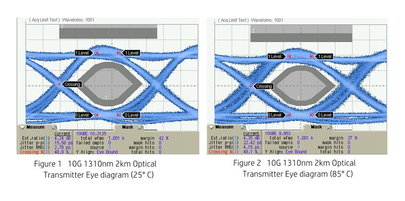
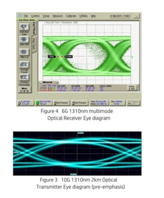
Generally, the optical eye and the electrical eye of the optical transceiver module with a transmission rate of less than 2.5Gb/s are easy to meet the requirement of the eye pattern. The eye line is usually a single line. However, the optical transceiver module with a transmission rate of 2.5Gb/s or more, Its eye diagram lines often appear double or multi-line. Figure 1, 2 are 10Gb/s 1310nm multi-mode optical transceiver module at 25 ℃ and 85 ℃ test results. Figure 2 Eye edge “hairiness” and eye pattern edge margin is poor than Figure 1. Figure 3 is a pre-emphasis 10Gb/s optical transceiver light eye diagram, the figure clearly shows the upper and lower left and right eyeliner has two. Figure 4 for the 6G, multi-mode, 1310nm optical receiver module electric eye diagram. In the figure, the rising edge of the eye is a thick, double hairline, and the descending edge appears to have a noticeable noise.
APD low-temperature light saturation problem
For high-speed xfp transceiver modules for engineering applications, we typically perform high and low-temperature cycling and storage tests at -40 ° C and 85 ° C. It was found that some products of 2.5Gb/s high sensitivity light receiving module with APD-TIA ROSA had low saturation optical power. That is, after storage at -40 ℃, part of the light receiving module saturation (or overload) optical power is low, lower than the relevant standard 8dBm optical power requirements, the test results shown in Table 1. In order to facilitate comparison, also listed at 25 ℃, 85 ℃ other optical receiver module sensitivity saturation optical power normal test results.
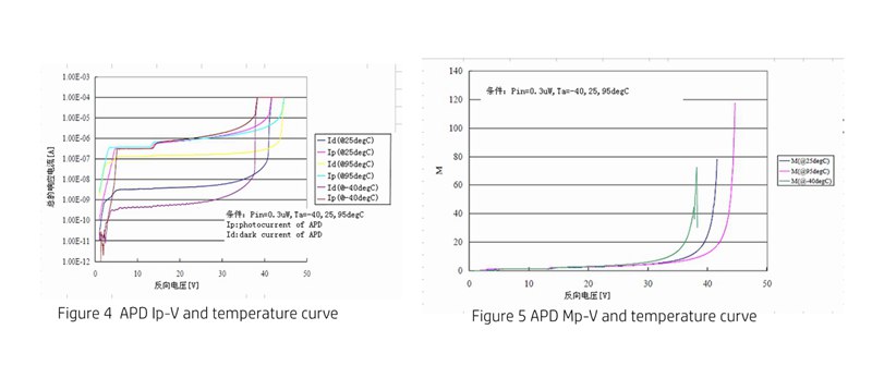
Table 1 shows that the light receiving sensitivity and saturation optical power of the 2.5Gb/s optical receiver module with APD-TIA ROSA meet the specified requirements at 25 ° C and 85 ° C ambient temperature, but some of the light receiving modules are at -40 ° C Under the saturation of optical power is less than -8dBm, does not meet the product saturation optical power requirements of indicators. This result seems to make people feel abnormal. It is generally believed that semiconductor photodetectors and microelectronic integrated circuits are temperature-sensitive devices, the lower the temperature, the photoelectric properties should Be better.
Analysis and discussion
On the eye diagram of two-line or multi-line in the optical communication digital signal transmission, detection, often observed eye pattern deformity or double line; for high-speed (such as 10Gb/s) signal, and sometimes can observe the eye line multi-line. They may result in a decrease in receiver sensitivity, an increase in transmission errors, and failure of the optical transceiver module. These eye lines may have many different forms of two or more lines. According to the test results, the two-line or multi-line can be divided into three categories:
1) single/double line, that is, the rising edge of the eyeliner was two lines, and the falling edge of a single line, as shown in Figure 1, 2
2) Double/double line, that is, the ascending / descending edge is two lines, and the other part is a single line; 3) the whole line, that is, eyeliner rise, falling edge, and other parts are two lines, as shown in Figure 2.
3) the whole line, that is, eyeliner rise, falling edge, and other parts are two lines, as shown in Figure 2.
There are many possible reasons for the formation of two or more lines in the eye; there are many different explanations or statements. Such as bandwidth limitation, impedance mismatch, pattern-dependent jitter, the extinction ratio is too large, digital circuit transistor saturation.
Our tests show that the extinction ratio is not too high, especially for the 10Gb/s medium and long distance optical transceiver, if the extinction ratio is greater than 12.0dB, the optical eye diagram will deteriorate sharply, resulting in light receiver sensitivity cannot be measured. This may be higher when the extinction is high, the laser carrier internal concentration changes rapidly, resulting in the laser active layer in the refractive index, light propagation constant, light pulse phase high-speed changes, causing the optical pulse signal edge shift and Redshift, resulting in deterministic jitter. This shows that the extinction ratio is not as high as possible, high-speed XFP transceiver module, the value is best not to exceed 12.5dB.
High, low temperature and multi-mode emission mode also have a significant impact on the eye. The 10G multimode 1310nm optical module was tested to show that although the optical power and extinction ratio were also met at 25 ° C, the eye pattern was deteriorated at high temperature (or low temperature) As shown in Figure 2. This may be due to high-frequency laser chirp and high-temperature degradation due to performance. It is worth noting that, in contrast, to test 10Gb 1550nm single-mode optical transceiver, regardless of low temperature or high temperature, no observation of multi-line eye. This shows that multi-mode caused by the dispersion may lead to the multi-line eye.
For high-speed optical transceiver module, in order to improve the sensitivity of optical reiceiver, often take pre-emphasis technology. Is to pulse the electrical modulation signal, first in its rise/fall along the superposition of a sharp pulse, in order to compensate for the high-frequency part of the pulse signal. Because of high-frequency signal transmission on the PCB, due to skin effect, high-frequency part of the resistance than the low-frequency part of the attenuation fast. Pre-emphasis technology, that is, before the signal transmission, first compensation signal in the high-frequency part. As the pre-emphasis is to take the waveform superposition method, the added graphics can easily lead to multiple paths of the signal, the launch eye diagram may seem more messy, as shown in Figure 2. But this light transmission signal through the optical fiber transmission and reception, the light received eye view but it is relatively clear, standardized. Therefore, the eye to distinguish treatment, serious identification, comprehensive consideration. As long as the final light to receive eye and sensitivity to meet the requirements on the line. As for the light emission eye diagram clear or not, not the ultimate goal. The ultimate goal is how the effect of fiber transmission, this is the correct way to judge the eye diagram.
As reported in the previous section, the partial light receiving modes with APDs exhibit low saturation optical power at low temperatures and may be a problem caused by APD temperature characteristics. Thus, the photocurrent (IP) and photomultiplier of APD were tested. The test results are shown in Figure 4,5. According to the test results, APD breakdown voltage Vbr, the optimal light multiplication M p.opt with temperature changes, we can see V br temperature change with the temperature coefficient (0.06-0.08) V / ℃, such as the temperature increased 60 ℃, then ΔV br will rise (3-4) V.
Conclusion
High-speed Optical transceiver module, because of the device temperature characteristics, transmission skin effect, system bandwidth constraints, assembly parasitic parameters, transmission impedance mismatch, extinction ratio caused by a large number of deterministic jitter, electromagnetic interference, and so on, often make some products ineffective. The low saturation light power caused by the multi-line and APD temperature characteristics is the two failure modes when the high-Speed Optical transceiver module is tested.
Pre-aggravation and equalization of transmission signals is a common method for high-speed optical transceiver modules. Pre-aggravation and balanced treatment should be moderate. Moderate or not, can be measured by the optical receiving eye diagram and the sensitivity of light reception. This is the correct way to identify whether or not the emitter eye is qualified.
Introduction
Optical communication technology to high-speed, high-capacity, small size, the high-density direction of development, new products continue to appear. In Gigabit optical access network, the High-speed optical transceiver module is the key component, and its performance and reliability are the two most concerned problems for the supplier and the user. The performance and reliability of optoelectronic devices and optical transceiver modules are not only related to product design, materials used, manufacturing conditions, process levels, working conditions and time, but also to the production environment and the fine spirit of the operators. In the industry competition, product reliability becomes more and more important.
For optoelectronic devices and optical transceivers, due to the structural tolerance has entered into the sub-millimeter (for PCB design), submicron (for optoelectronic chips) level, requiring the workpiece to be non-polluting, structurally complex processes long, and some products are defective or insufficient. These defects or deficiencies, in the harsh external conditions (such as temperature, humidity, stress, electromagnetic interference) will continue to expand, resulting in product features and photoelectric performance changes do not meet the requirements of the product requirements, resulting in product failure. The failure mode is the form of product failure, including in the force (mechanical), electricity, light, heat, magnetic, and the performance of the form. Through the detection, field use and reliability test, you can find a variety of product failure mode. The relevant international and domestic standards specify the reliability test and requirements for optoelectronic devices. Through the reliability test and failure analysis, the improvement measures and verification, product reliability is expected to continue to improve.
However, the reliability of some products has been solved and the reliability of new products has arisen. In this paper, we first introduce the General failure mode classification and common failure modes of optical communication optoelectronic devices/Optical transceiver modules and report and analyze two new failure modes in order to help to analyze the failure mechanism and propose improvement measures.
General failure mode classification and common failure modes of optical devices and transceiver
Many failure modes exist in optical communication in optical devices and optical transceiver modules. According to the general classification method, they can be divided into different categories.
According to the failure of products (including semi-finished) varieties to classify, can be divided into chip failure, component failure, PCB circuit failure, fiber testing failure and other failures.
According to the failure generation stage, can be divided into Design potential failure, process failure, use (specified environment) failure.
According to the failure components and parts, can be divided into microelectronics and optoelectronic chip failure, optoelectronic components (including optical path) failure, PCB (especially high-speed circuit) failure, optical coupling and encapsulation failure.
According to the production process of failure, can be divided into optoelectronic chip production failure, circuit design and PCB production failure, device/component assembly failure, device coupling packaging failure, debugging and fiber transfer process failure.
In short, a lot of failure modes, varied, involving light, electricity, power, heat, magnetic and other fields. Each type of failure can be divided into many different subclasses.
According to the above process of failure of the device/component assembly failure, can be divided into the following failure mode sub-categories and common failure mode:
Viscose and welding failure, there are: insufficient amount of glue, glue too much, the pin sticky glue, the base sticky glue, glue is not insulated, lens off, solder is not molten, solder spill, high solder joints, solder joints Low, solder bump, solder crack, solder joint, welding oxidation, pipe sticky crooked and so on.
The failure of the gold wire in the hot press is: the wire is broken, the gold wire is deformed, the tension is insufficient, the lead/pin is too long; it is worth noting that the lead/pin is too long to produce additional inductance, High-speed component transmission failure in a difficult problem.
Laser package failure in the welding, there are: base scratches, lens damage, lens contamination, pin damage, face defects, indentation, body without solder, solder joints, cracks, welding bubbles, welding oxidation, too many solder joints, laser beam less coke or over coke, welding gap and so on.
According to our existing practice, optoelectronic devices / optical transceiver module common problems and failure modes are:
Optoelectronic device problems such as LD, PIN internal defects, face or surface contamination, LD jump mode or wavelength drift; photodiode reverse breakdown or leakage large;
Fiber issues: such as fiber end contamination, fiber micro-displacement (resulting in tracking error), fiber break;
Assembly and packaging issues: such as viscose problems, wire/lead too long, Weld or oxidation, laser welding cracks, poor sealing;
Optical performance problems such as optical power, extinction ratio, return loss, receiver sensitivity, ESD problem
Signal integrity issues such as reflection, electromagnetic interference, power ripple, synchronous switching noise;
Eye problems: such as eyeliner red/tail, signal distortion, jitter, noise and so on
High and low-temperature performance problems such as LD power reduction/threshold current increase, reiver sensitivity degradation, transmission loss, etc.
For the high-Speed Optical transceiver module, in addition to the common problems and failure modes mentioned above, some new failure modes are also found. The following is an introduction and preliminary analysis of two new failure modes.
Eye diagram multi-line
We know that the eye diagram is the digital signal (the general NRZ code) of the many unit serial graphics superposition, because the graphics similar to the eye, it is called eye diagram. It fully characterizes the bit information of the serial signal, and becomes a simple and important tool to measure the signal quality, and is the most direct and effective method for the transmission performance observation of binary digital signals. In order to facilitate the rapid evaluation of eye diagram quality, the different rates, the different photoelectric performance of the optical transceiver module, the relevant standards set a measure of the eye map qualified or not “eye pattern.”
Generally, the optical eye and the electrical eye of the optical transceiver module with a transmission rate of less than 2.5Gb/s are easy to meet the requirement of the eye pattern. The eye line is usually a single line. However, the optical transceiver module with a transmission rate of 2.5Gb/s or more, Its eye diagram lines often appear double or multi-line. Figure 1, 2 are 10Gb/s 1310nm multi-mode optical transceiver module at 25 ℃ and 85 ℃ test results. Figure 2 Eye edge “hairiness” and eye pattern edge margin is poor than Figure 1. Figure 3 is a pre-emphasis 10Gb/s optical transceiver light eye diagram, the figure clearly shows the upper and lower left and right eyeliner has two. Figure 4 for the 6G, multi-mode, 1310nm optical receiver module electric eye diagram. In the figure, the rising edge of the eye is a thick, double hairline, and the descending edge appears to have a noticeable noise.
APD low-temperature light saturation problem
For high-speed xfp transceiver modules for engineering applications, we typically perform high and low-temperature cycling and storage tests at -40 ° C and 85 ° C. It was found that some products of 2.5Gb/s high sensitivity light receiving module with APD-TIA ROSA had low saturation optical power. That is, after storage at -40 ℃, part of the light receiving module saturation (or overload) optical power is low, lower than the relevant standard 8dBm optical power requirements, the test results shown in Table 1. In order to facilitate comparison, also listed at 25 ℃, 85 ℃ other optical receiver module sensitivity saturation optical power normal test results.
Table 1 shows that the light receiving sensitivity and saturation optical power of the 2.5Gb/s optical receiver module with APD-TIA ROSA meet the specified requirements at 25 ° C and 85 ° C ambient temperature, but some of the light receiving modules are at -40 ° C Under the saturation of optical power is less than -8dBm, does not meet the product saturation optical power requirements of indicators. This result seems to make people feel abnormal. It is generally believed that semiconductor photodetectors and microelectronic integrated circuits are temperature-sensitive devices, the lower the temperature, the photoelectric properties should Be better.
Analysis and discussion
On the eye diagram of two-line or multi-line in the optical communication digital signal transmission, detection, often observed eye pattern deformity or double line; for high-speed (such as 10Gb/s) signal, and sometimes can observe the eye line multi-line. They may result in a decrease in receiver sensitivity, an increase in transmission errors, and failure of the optical transceiver module. These eye lines may have many different forms of two or more lines. According to the test results, the two-line or multi-line can be divided into three categories:
1) single/double line, that is, the rising edge of the eyeliner was two lines, and the falling edge of a single line, as shown in Figure 1, 2
2) Double/double line, that is, the ascending / descending edge is two lines, and the other part is a single line; 3) the whole line, that is, eyeliner rise, falling edge, and other parts are two lines, as shown in Figure 2.
3) the whole line, that is, eyeliner rise, falling edge, and other parts are two lines, as shown in Figure 2.
There are many possible reasons for the formation of two or more lines in the eye; there are many different explanations or statements. Such as bandwidth limitation, impedance mismatch, pattern-dependent jitter, the extinction ratio is too large, digital circuit transistor saturation.
Our tests show that the extinction ratio is not too high, especially for the 10Gb/s medium and long distance optical transceiver, if the extinction ratio is greater than 12.0dB, the optical eye diagram will deteriorate sharply, resulting in light receiver sensitivity cannot be measured. This may be higher when the extinction is high, the laser carrier internal concentration changes rapidly, resulting in the laser active layer in the refractive index, light propagation constant, light pulse phase high-speed changes, causing the optical pulse signal edge shift and Redshift, resulting in deterministic jitter. This shows that the extinction ratio is not as high as possible, high-speed XFP transceiver module, the value is best not to exceed 12.5dB.
High, low temperature and multi-mode emission mode also have a significant impact on the eye. The 10G multimode 1310nm optical module was tested to show that although the optical power and extinction ratio were also met at 25 ° C, the eye pattern was deteriorated at high temperature (or low temperature) As shown in Figure 2. This may be due to high-frequency laser chirp and high-temperature degradation due to performance. It is worth noting that, in contrast, to test 10Gb 1550nm single-mode optical transceiver, regardless of low temperature or high temperature, no observation of multi-line eye. This shows that multi-mode caused by the dispersion may lead to the multi-line eye.
For high-speed optical transceiver module, in order to improve the sensitivity of optical reiceiver, often take pre-emphasis technology. Is to pulse the electrical modulation signal, first in its rise/fall along the superposition of a sharp pulse, in order to compensate for the high-frequency part of the pulse signal. Because of high-frequency signal transmission on the PCB, due to skin effect, high-frequency part of the resistance than the low-frequency part of the attenuation fast. Pre-emphasis technology, that is, before the signal transmission, first compensation signal in the high-frequency part. As the pre-emphasis is to take the waveform superposition method, the added graphics can easily lead to multiple paths of the signal, the launch eye diagram may seem more messy, as shown in Figure 2. But this light transmission signal through the optical fiber transmission and reception, the light received eye view but it is relatively clear, standardized. Therefore, the eye to distinguish treatment, serious identification, comprehensive consideration. As long as the final light to receive eye and sensitivity to meet the requirements on the line. As for the light emission eye diagram clear or not, not the ultimate goal. The ultimate goal is how the effect of fiber transmission, this is the correct way to judge the eye diagram.
As reported in the previous section, the partial light receiving modes with APDs exhibit low saturation optical power at low temperatures and may be a problem caused by APD temperature characteristics. Thus, the photocurrent (IP) and photomultiplier of APD were tested. The test results are shown in Figure 4,5. According to the test results, APD breakdown voltage Vbr, the optimal light multiplication M p.opt with temperature changes, we can see V br temperature change with the temperature coefficient (0.06-0.08) V / ℃, such as the temperature increased 60 ℃, then ΔV br will rise (3-4) V.
Conclusion
High-speed Optical transceiver module, because of the device temperature characteristics, transmission skin effect, system bandwidth constraints, assembly parasitic parameters, transmission impedance mismatch, extinction ratio caused by a large number of deterministic jitter, electromagnetic interference, and so on, often make some products ineffective. The low saturation light power caused by the multi-line and APD temperature characteristics is the two failure modes when the high-Speed Optical transceiver module is tested.
Pre-aggravation and equalization of transmission signals is a common method for high-speed optical transceiver modules. Pre-aggravation and balanced treatment should be moderate. Moderate or not, can be measured by the optical receiving eye diagram and the sensitivity of light reception. This is the correct way to identify whether or not the emitter eye is qualified.
RECENT BLOG POST
-
012019-10With the continuous development of 5G communication technology, 100G modules are gradually becoming popular. We know that there are many kinds of packages for 100G optical modules. From 2000 to now, the optical module package types have been rapidly developed. Its main package types are: GBIC, SFP, XENPAK, SNAP12, X2, XFP, SFP+, QSFP/QSFP+, CFP, CXP. In the fast-developing network era, some 100G optical modules avoid the risk of being eliminated, and upgraded and revised with the wave of the Internet, such as 100G CFP optical modules.
-
012019-101. What is the CWDM SFP? The CWDM optical module is an optical module using CWDM technology to implement the connection between the existing network device and the CWDM multiplexer/demultiplexer. When used with a CWDM multiplexer/demultiplexer, CWDM optical modules can increase network capacity by transmitting multiple data channels with separate optical wavelengths (1270 nm to 1610 nm) on the same single fiber.
-
012019-10AOC is the abbreviation of Active Optical Cables, which is called Active Optical Cables in Chinese. AOC active optical is to encapsulate two optical modules and cable together. Because the medium of transmission in the middle is optical cable, AOC optical module, which contains laser devices, has a higher price for DAC. However, its optical aperture is not exposed, it has high reliability, and its working distance can be customized for a long distance of less than 100 meters.
-
012019-10Dense Wavelength Division Multiplexing (DWDM) technology is capable of transmitting data in an optical fiber using bit wavelength parallel transmission or string line transmission using the wavelength of the laser.It is widely used in different fields of communication networks, including long-distance backbone networks, metropolitan area networks (MANs), residential access networks, and local area networks (LANs).The DWDM optical module is the optical module that uses this technology, so the DWDM optical module has high bandwidth and long-distance transmission characteristics.


