
Fiber Link Power Budget: How to Make It Right?
2017-06-25
In optical communication system, fiber patch cables and optical transceivers are necessities to complete the pathway for optical signal, enabling data to transmit between devices. To ensure that the fiber system has sufficient power for correct operation, it is vitally important to calculate the span’s power budget. A solid fiber link performance assures the networks run smoother and faster, with less downtime. This article addresses the essential elements associated with link power budget, and illustrates how to calculate power budget effectively.
Power Budget Definition
Power budget refers to the amount of loss a data link can tolerate while maintaining proper operation. In other words, it defines the amount of optical power available for successful transmitting signal over a distance of optical fiber. Power budget is the difference between the minimum (worst case) transmitter output power and the maximum (worst case) receiver input required. The calculations should always assume the worst-case values, in order to ensure the availability of adequate power for the link, which means the actual value will always be higher than this. Optical power budget is measured by dB, which can be calculated by subtracting the minimum receiver sensitivity from the minimum transmit power:
PB (dB) = PTX (dBm) – PRX (dBm)
Why Does Power Budget Matter?
The purpose of power budgeting is to ensure that the optical power from transmission side to receiver is adequate under all circumstances. As data centers migrate to 40G, 100G and possible 400G in the near future, link performance becomes increasingly essential. Link failures would stir up a sequence of problems like system downtime, which equates to accelerated costs, frustrated users, deteriorated performance and increased total cost. While with appropriate power budgeting, a high-performance link can be achieved for better network reliability, more flexible cabling and simplified regular maintenance, which is beneficial in the long run.
Critical Elements Involved In Calculating Power Budget
When performing power budget calculation, there are a long list of elements to account for. The basic items that determine general transmission system performance are listed here.
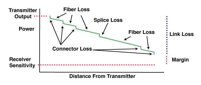
Fiber loss: fiber loss impacts greatly on overall system performance, which is expressed by dB per kilometer. The total fiber loss is calculated based on the distance × the loss factor (provided by manufacturer).
Connector loss: the loss of a mated pair of connectors. Multimode connectors will have losses of 0.2-0.5 dB typically. Single-mode connectors, which are factory made and fusion spliced on will have losses of 0.1-0.2 dB. Field terminated single-mode connectors may have losses as high as 0.5-1.0 dB.
Number and type of splices: Mechanical splice loss is generally in a range of 0.7 to 1.5 dB per connector. Fusion splice loss is between 0.1 and 0.5 dB per splice. Because of their limited loss factor, fusion splices are preferred.
Power margin: power budget margin generally includes aging of the fiber, aging of the transmitter and receiver components, additional devices, incidental twisting and bending of the fiber, additional splices, etc. The margin is needed to compensate for link degradation, which is within the range of 3 to 10 dB.
How to Properly Calculate Power Budget?
Here we use the following example to demonstrate how to calculate power budget of an optical link: Example: the system contains the transmitter and receiver, the optical link contains optical amplifier, 4 optical connectors and 5 splices. The following table presents attenuation or gain of each components.
Tx power: 3dBm
Connector loss: 0.15dB
Splice loss: 0.15dB
Amplifier gain: 10dB
Fiber optic loss: 0.2 dB/km
fiber link power budget calculation
The total attenuation of this link PL is the sum of:
Fiber optic loss: (30 km + 50 km) ×0.2dB/km = 16 dB
Attenuation of connectors: 4×0.15 dB = 0.60 dB
Attenuation of splices: 5×0.15 dB = 0.75 dB
So PL = 16 Db + 0.60 Db + 0.75 Db = 17.35 dB
The total gain of the link is generated by optical amplifier, which is 10 dB in this case. So PG = 10 dB
Considering link degradation, power margin should be calculated as well. A good safety margin PM = 6 dB
To select the receiver’s sensitivity at the end of the optical path, it is sufficient to rearrange and solve the equation. So:
Ptx – Prx < PL – PG + PM
Prx > Ptx – PL + PG – PM
Prx > 3 dBm – 17.35 dB +10 dB – 6 dB
Prx > -10.35 dB
The receiver should provide sensitivity better than -10.35 dBm.
Conclusion
With data centers migrating to 40G, 100G, 200G and even 400G, fiber link performance becomes more important than ever before. Understanding link power budget will help you optimize your fiber link design as well. In addition, high-performance cables, quality transceivers and high-performance installation practices also assist to ensure better link performance.
SFP+ module,SFP+ transceiver,bidi sfp,XFP module,XFP transceiver Which is good? First choice Fiberland!Thanks for your concern, to learn more about Fiberland, please enter Fiberland website: http://www.fiberlandtec.com/
Power Budget Definition
Power budget refers to the amount of loss a data link can tolerate while maintaining proper operation. In other words, it defines the amount of optical power available for successful transmitting signal over a distance of optical fiber. Power budget is the difference between the minimum (worst case) transmitter output power and the maximum (worst case) receiver input required. The calculations should always assume the worst-case values, in order to ensure the availability of adequate power for the link, which means the actual value will always be higher than this. Optical power budget is measured by dB, which can be calculated by subtracting the minimum receiver sensitivity from the minimum transmit power:
PB (dB) = PTX (dBm) – PRX (dBm)
Why Does Power Budget Matter?
The purpose of power budgeting is to ensure that the optical power from transmission side to receiver is adequate under all circumstances. As data centers migrate to 40G, 100G and possible 400G in the near future, link performance becomes increasingly essential. Link failures would stir up a sequence of problems like system downtime, which equates to accelerated costs, frustrated users, deteriorated performance and increased total cost. While with appropriate power budgeting, a high-performance link can be achieved for better network reliability, more flexible cabling and simplified regular maintenance, which is beneficial in the long run.
Critical Elements Involved In Calculating Power Budget
When performing power budget calculation, there are a long list of elements to account for. The basic items that determine general transmission system performance are listed here.
Fiber loss: fiber loss impacts greatly on overall system performance, which is expressed by dB per kilometer. The total fiber loss is calculated based on the distance × the loss factor (provided by manufacturer).
Connector loss: the loss of a mated pair of connectors. Multimode connectors will have losses of 0.2-0.5 dB typically. Single-mode connectors, which are factory made and fusion spliced on will have losses of 0.1-0.2 dB. Field terminated single-mode connectors may have losses as high as 0.5-1.0 dB.
Number and type of splices: Mechanical splice loss is generally in a range of 0.7 to 1.5 dB per connector. Fusion splice loss is between 0.1 and 0.5 dB per splice. Because of their limited loss factor, fusion splices are preferred.
Power margin: power budget margin generally includes aging of the fiber, aging of the transmitter and receiver components, additional devices, incidental twisting and bending of the fiber, additional splices, etc. The margin is needed to compensate for link degradation, which is within the range of 3 to 10 dB.
How to Properly Calculate Power Budget?
Here we use the following example to demonstrate how to calculate power budget of an optical link: Example: the system contains the transmitter and receiver, the optical link contains optical amplifier, 4 optical connectors and 5 splices. The following table presents attenuation or gain of each components.
Tx power: 3dBm
Connector loss: 0.15dB
Splice loss: 0.15dB
Amplifier gain: 10dB
Fiber optic loss: 0.2 dB/km
fiber link power budget calculation
The total attenuation of this link PL is the sum of:
Fiber optic loss: (30 km + 50 km) ×0.2dB/km = 16 dB
Attenuation of connectors: 4×0.15 dB = 0.60 dB
Attenuation of splices: 5×0.15 dB = 0.75 dB
So PL = 16 Db + 0.60 Db + 0.75 Db = 17.35 dB
The total gain of the link is generated by optical amplifier, which is 10 dB in this case. So PG = 10 dB
Considering link degradation, power margin should be calculated as well. A good safety margin PM = 6 dB
To select the receiver’s sensitivity at the end of the optical path, it is sufficient to rearrange and solve the equation. So:
Ptx – Prx < PL – PG + PM
Prx > Ptx – PL + PG – PM
Prx > 3 dBm – 17.35 dB +10 dB – 6 dB
Prx > -10.35 dB
The receiver should provide sensitivity better than -10.35 dBm.
Conclusion
With data centers migrating to 40G, 100G, 200G and even 400G, fiber link performance becomes more important than ever before. Understanding link power budget will help you optimize your fiber link design as well. In addition, high-performance cables, quality transceivers and high-performance installation practices also assist to ensure better link performance.
SFP+ module,SFP+ transceiver,bidi sfp,XFP module,XFP transceiver Which is good? First choice Fiberland!Thanks for your concern, to learn more about Fiberland, please enter Fiberland website: http://www.fiberlandtec.com/
RECENT BLOG POST
-
012019-10With the continuous development of 5G communication technology, 100G modules are gradually becoming popular. We know that there are many kinds of packages for 100G optical modules. From 2000 to now, the optical module package types have been rapidly developed. Its main package types are: GBIC, SFP, XENPAK, SNAP12, X2, XFP, SFP+, QSFP/QSFP+, CFP, CXP. In the fast-developing network era, some 100G optical modules avoid the risk of being eliminated, and upgraded and revised with the wave of the Internet, such as 100G CFP optical modules.
-
012019-101. What is the CWDM SFP? The CWDM optical module is an optical module using CWDM technology to implement the connection between the existing network device and the CWDM multiplexer/demultiplexer. When used with a CWDM multiplexer/demultiplexer, CWDM optical modules can increase network capacity by transmitting multiple data channels with separate optical wavelengths (1270 nm to 1610 nm) on the same single fiber.
-
012019-10AOC is the abbreviation of Active Optical Cables, which is called Active Optical Cables in Chinese. AOC active optical is to encapsulate two optical modules and cable together. Because the medium of transmission in the middle is optical cable, AOC optical module, which contains laser devices, has a higher price for DAC. However, its optical aperture is not exposed, it has high reliability, and its working distance can be customized for a long distance of less than 100 meters.
-
012019-10Dense Wavelength Division Multiplexing (DWDM) technology is capable of transmitting data in an optical fiber using bit wavelength parallel transmission or string line transmission using the wavelength of the laser.It is widely used in different fields of communication networks, including long-distance backbone networks, metropolitan area networks (MANs), residential access networks, and local area networks (LANs).The DWDM optical module is the optical module that uses this technology, so the DWDM optical module has high bandwidth and long-distance transmission characteristics.


